Vibration & Ultrasound Technologies: A Possible Integrated Inspection Tool?
Stuart Courtney
Introduction
The purpose of this paper is to introduce condition monitoring and reliability engineers to the principles of using ultrasound technologies for the assessment of machine condition. Ultrasound can be a complimentary technology to vibration, thermography and lubrication monitoring. It must be emphasized that it is rarely successful as a stand alone technology for effective machine condition assessment and subsequent required maintenance planning. This paper concentrates on the use of airborne ultrasound as a complementary technique particularly for machinery that may be inaccessible due to guards or hazardous locations.
What is Ultrasound?
Ultrasound is defined as high-frequency sound waves, which are above the range of human perception. Usually they start at 20 kilohertz (kHz) and go up into the megahertz range. Airborne/ Structure borne ultrasound covers frequencies from 20 kHz up to 300 kHz.
How Does the Instrumentation Work?
Airborne/structure-borne ultrasound instruments provide information through multiple paths: qualitatively through their ability to hear ultrasounds through a noise-isolating headphone, and quantitatively via incremental readings on a meter/display panel. Digital instruments provide on-board data storage for data logging and for viewing baseline data. Some newer versions of the instruments also include on-board sound recording for spectral analysis.
The instruments allow inspectors to confirm a diagnosis on the spot because they clearly discriminate among various equipment sounds. An electronic process called “heterodyning” accurately converts ultrasounds sensed by the instrument into the audible range where users can hear and recognize them through headphones. This process enables users to record sound events through conventional recording devices.
Most of the sounds sensed by humans range between 20 Hertz and 20 kilohertz. (The average high-end human threshold is16.5 kHz.) The wavelength sizes of these frequencies tend to be relatively large when compared with the sizes of sound waves sensed by ultrasonic translators. The wavelength of low-frequency sounds in the audible range are approximately 1.9 cm (3/4″) up to 17 m (56′) in length (when using the high-frequency average of 16.5 kHz), whereas ultrasounds sensed by ultrasonic detectors are only 0.3 cm (1/8″) up to 1.6 cm (5/8″) long. Since ultrasound wavelengths are magnitudes smaller than those in the audible range, they have characteristics that are conducive to condition analysis. One advantage is that the amplitude of a generated ultrasound falls off exponentially from the source, making the emission localized and easily isolated for detection and analysis.
The AE technique homes directly in on the high frequency (~ 100 kHz) component of the elastic waves being generated by operating machinery. The resulting AE signal is very strongly influenced by fault processes and has a much reduced sensitivity to the effects of normal running components. (ie good machines are much quieter at 100 kHz yet machine faults which result in deteriorating contacting surface give rise to very loud signals). Because of this it is possible to analyze the ultrasound signal
Connection to a Data Collector
Ultrasound technologies have an output that can be connected to a vibration data collector. The setup will be pretty much the same for all and what you do with the signal will also be pretty much the same.
Examples of how to connect ultrasonic detectors to a data collector can be obtained from equipment manufacturers. All connect in a similar way and will give similar results.
Analysis
The output of most ultrasonic detectors is a heterodyned signal so you could look at the signal as a direct representation and scale the values in an engineering unit such as volts, Eus, or even Gs. The definition of the parameter is arbitray as it is really has no meaning as an amplitude value. This is purely used for a one shot analysis function.
Much better analysis can be performed by using a system of enveloping which is somewhat similar to heterodyning. Enveloping is a demodulation process that is used predominantly to measure the incipient defects that are present when a rolling element bearing starts to fail. There are many different types of enveloping and many of them can be applied to ultrasonic detectors. By using the enveloping circuit of the data collector you effectively double envelope the high frequency system. The important thing to remember is that we are looking at early deterioration of the rolling element bearing or its lubrication film. The fluid film thickness in a rolling element bearing is less than one micron, if there is a breakdown of the film due to lack of lubrication or parasitic loads
Detecting bearing failure is relatively easy; careful choices need to be made if detection of bearing problems is the requirement. Ultrasound can be one method of determining when bearings are suffering from poor lubrication or subsurface fretting of the structure of the bearing metals.
There are some technologies that are direct reading from a sensor these can be more easily used in a condition monitoring regime as they are trend-able and scalable.
Examples
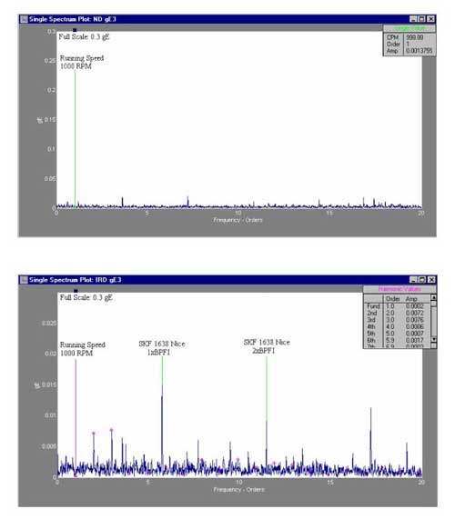
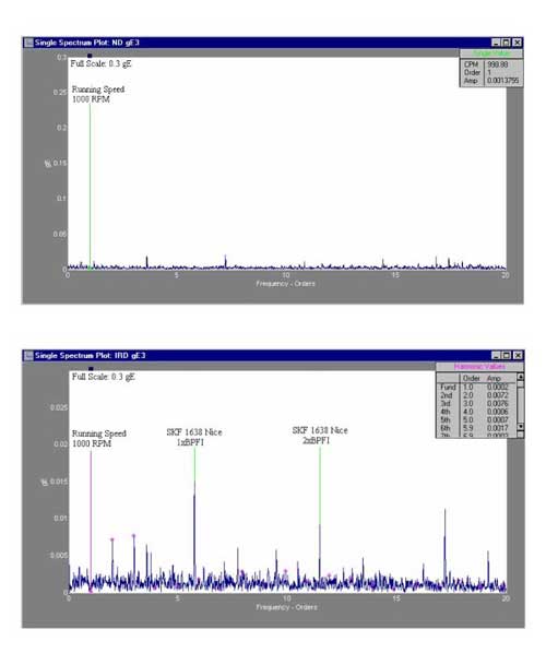
In order to demonstrate the difference in monitoring a bearing using a vibration sensor and airborne ultrasound a bearing was monitored when it was first installed and then when it was in its primary failure mode.
Pitfalls
It is generally difficult to trend the output of ultrasonic detectors, the units are not scalable and will vary dependant how far the sensor is positioned from the bearing being measured.
The ultrasound detector is directional and care has to be taken to ensure that the source of ultrasound id effectively monitored.
Conclusions
Supplementing vibration testing with spectral analysis of the output signal from the ultrasonic detector can be a helpful tool when used for the analysis of bearing and other types of mechanical faults. Some ultrasound technologies detect frequencies centered at 40 kHz ± 20 kHz. Others have tunable filters, they are generally all suitable for problem finding in a condition monitoring based reliability regime. The ultrasonic signals are demodulated to produce an audible signal, which are heard using the headphone or viewed using the data collector. The amplitudes of the spectrums not only depend on the severity but also depend on the medium that the signals are traveling through. As a result the data is not easily scalable and therefore difficult to trend. Nevertheless by using the data collector the spectral data can be analyzed and the cause of the machine problem can be determined. The bearing defect frequencies can be heard and their spectrum viewed even by taking the data as much as 10 feet away. Practically the machine analyst could rapidly scan the machine with the ultrasonic detector and the headset. When an unusual sound from a bearing is detected, then a data collector measurement will provide the analyst with useful data. For the usual data collection including trending, the data collector and an accelerometer is still the best choice.
Related Articles
Principles of Insulation Testing
Top Tips for Selecting Pressure Measurement Transmitters
Gearbox Diagnostics Fault Detection
What is Vibration?

Why Record? Infrared Video