Vibration Analysis Reveals Poor Motor Mounting Structure
www.reliabilityworld.com
At the installation of a new 150 gal/min centrifugal pump driven by a 125 HP motor, high vibration levels were found immediately upon first start. After several days of alignment checks, pump teardowns, bearing inspections, motor uncoupled runs and vendor technical support, no solution was found. The plant maintenance manager asked the company’s vibration analyst to take readings to troubleshoot the problem. After measuring extremely high vibration levels, resonance was suspected and was found at the motor support structure due to inadequate mounting design for the new installation.
Figure 1
The company’s vibration analyst took readings on the horizontal pump/motor unit and found extremely high vibration levels focused in the horizontal direction at the motor bearings on the order of 1 in/sec velocity with only 0.2 in/sec vertically. Directional resonance was immediately suspected.
The analyst shutdown the unit immediately and performed a visual inspection of the motor support structure. Twin “C” channel beams were set to the foundation parallel, supporting one front and one back foot on the motor on either side. No cross support was present and the six inches under the motor was wide open.
Seeing this, the analyst performed a simple bump test with the unit off and found a natural frequency at 3,600 cycles per minute in a horizontal direction on the motor. The running speed of the motor was 3,585 RPM fully loaded, which provides the driving force necessary to excite this natural frequency resulting in a resonant condition. The bump test involves placing a vibration sensor in the direction of interest and exciting the system with a three-pound rubber hammer to excite random vibration in the range of motor/pump driving frequencies. A good kick will do the same thing.
The vendor-designed motor support was then temporarily stiffened through the use of a porta-power ram and the unit was started to confirm this resonance condition existed. The resulting vibration levels in the horizontal direction dropped to 0.085 in/sec, confirming an inadequate support design for the motor.
The final fix involved welding bracing across the “C” channel at both the front and back feet areas of the motor, creating a box support. This resulted in an even further reduction in vibration levels and eliminated the resonant condition after only three hours of troubleshooting and repair, compared to the three days of repeated teardowns and reassembly upon initial installation due to high vibration.
The lack of detailed specifications for installation of new machinery provided to a vendor permits poor installation designs which have repeatedly resulted in resonance situations and early failure of associated components in numerous installations.
Acceptance testing of all new installations and repairs by vendors is an integral piece in the care of company assets which, though not in place at this time, was used by plant personnel who refused to accept the extreme vibration felt by hand and requested vendor action.
Our company is now actively pursuing new installation guidelines (on the order of API Recommended Practice 686), repair guidelines with root cause analysis findings and acceptance criteria on new and rebuilt equipment and installations.
Related Articles
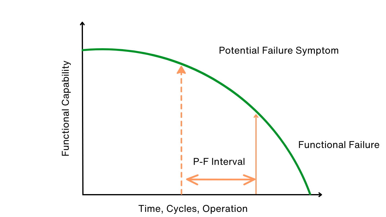
Use P-F Intervals to Map, Avert Failures

The RCM Trap


Can You Really Justify Reliability Centered Maintenance (RCM)?

Design for Maintainability