Top Tips for Selecting Pressure Measurement Transmitters
www.engineerlive.com
The first stage in selecting pressure measurement transmitters is whether to opt for a transducer or a transmitter. Although the terms are often confused, there are several differences between transducer and transmitter devices. A transducer creates a low-level electronic signal in response to changes in applied or differential pressure. As with transmitters, transducers feature an internal sensor that converts the applied force into an electrical signal, from which the measurement is derived.
Transducers are generally unsuitable for the harsh environments typical of many industrial applications. The transducer body is usually small and cannot easily be fitted to standard industrial piping. They are also commonly poorly protected against the effects of overpressure or damage caused by sudden variations in process conditions.
Transducers also have inferior stability and measurement accuracy compared to transmitters. They offer limited compensation for variations in process or ambient conditions such as temperature and are often fixed range devices, which can only measure within a set span.
Transmitters for measuring pressure or differential pressure, on the other hand, comprise two basic parts. A primary element directly or indirectly in contact with the process collects the measurement, while a secondary electronics package translates the output from the primary element into a standard 4–20mA dc output signal.
These secondary electronics are highly sophisticated and perform many functions that transducers cannot. Variations in process or ambient conditions measured by the primary sensor can be automatically compensated for before being converted into a 4–20mA signal.
This minimises unwanted measurement errors and gives the transmitter a very stable output. Operators can also calibrate the transmitter over a range of input pressures, enabling one unit to be used to measure a range of spans.
Operating Environment for Pressure Measurement Transmitters
Modern pressure measurement transmitters should be able to comfortably handle adverse temperatures, humidity and vibration conditions provided they are within design specification limits. Minimising the effects of such conditions will help to maximise the transmitters operational life.
Most electronic transmitters are suitable for conditions ranging from lows of -20°C to -40°C to highs of 60°C to 85°C, although this may not always be the case for certain types, for example where special filling materials have been specified for the transmitter. An application’s ambient temperature conditions can significantly affect transmitter efficiency. This can include not just the inherent background temperature of the installation location, but also heat generated from a process or radiated from surrounding process equipment and piping. High temperatures can have a detrimental effect, potentially causing premature component failure. Ideally, the temperature of the transmitter should be kept as low as possible for maximum life expectancy. Careful consideration also needs to be exercised when installing a transmitter outdoors. Atmospheric conditions such as direct sunlight or high winds can cause heating or cooling of transmitters, which can adversely affect their operation.
Then there is humidity. Vapour caused by humid conditions can sometimes penetrate the transmitter housing and attack sensitive components. Prolonged exposure to high humidity can also result in corrosion of the transmitter housing and mountings. Transmitter housings are designed to protect electrical components against the ingress of moisture caused by humidity. However, even housings with a NEMA rating for moisture or hosedown applications can encounter problems if the housing cover is removed during commissioning, operation or maintenance. Some manufacturers employ various methods such as using potting material to protect transmitter electronics against humidity. Whilst they can delay humidity problems, these methods do not provide a long-term solution. The only true prevention against humidity is for the transmitter housing to be hermetically sealed.
Vibration is another issue. Avoid installing a transmitter in an area subject to prolonged or unnecessary levels of vibration, as this can reduce the service life of the transmitter. To protect against potential damage or malfunction caused by vibration, transmitters should be mounted in a location that will be unaffected by vibration when a process is in operation.
Two wire, four wire or digital?
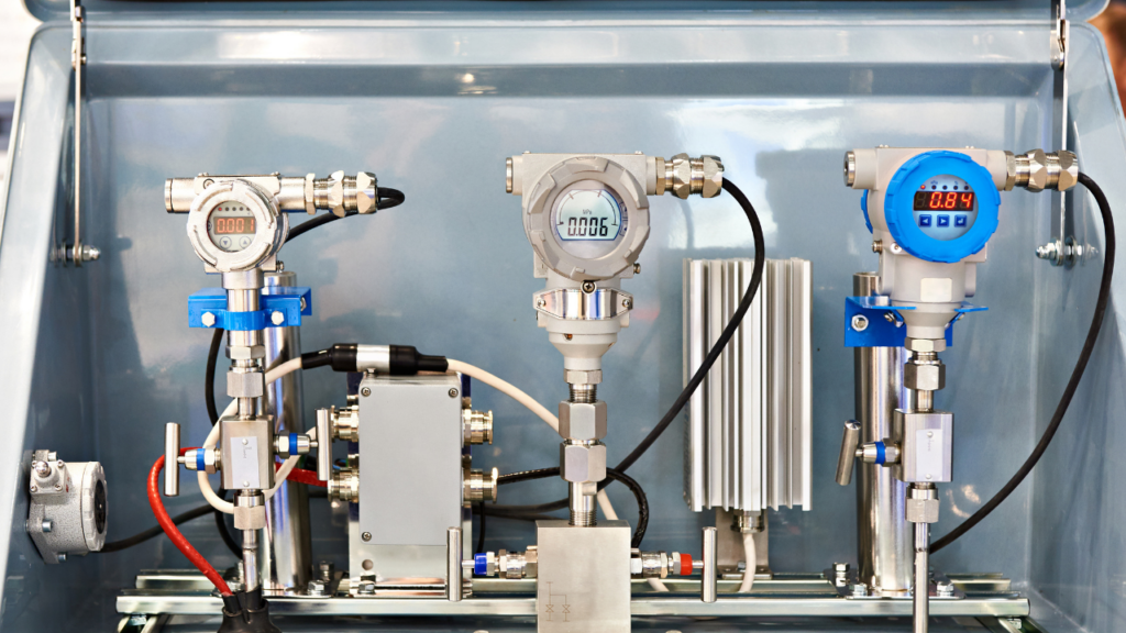
There are many different types of transmitters, each of which use different techniques to transmit a signal (Fig.1). The role of the transmitter is to amplify and condition the signal so that it can be relayed over long distances to devices such as indicators, recorders and controllers without deterioration or interference.
For the majority of applications where power is readily available, the two-wire transmitter, which uses a 4–20mA current both to operate its circuitry and to relay a signal, is often the most practical choice. Because the current is protected against the effects of changing resistance along the line, signals can be relayed over long distances.
For applications where a ready supply of power is not available, such as remote installations, then a low powered four-wire electronic transmitter is the best choice.
Four-wire devices use two wires to power the instrument and two wires to transmit the signal. These low powered pressure measurement transmitters typically consume about one-tenth of the energy of standard two-wire transmitters under normal operating conditions. Despite consuming less energy, they are only really suitable for applications where the devices to which they are to be connected are close by. This is because long transmission distances produce a loss of voltage signal due to the internal resistance drop in the line, affecting measurement accuracy.
Where high-speed transmission of accurate data is essential, the best choice is to opt for digital transmitters, which transmit both digital and analogue signals via a two-wire link. Digital signal transmission is faster and more accurate than analogue and allows much more data to be relayed between the instrument and the control room.
All transmitters within ABB’s 2600T range are available with a choice of communications standards including HART/4–20mA, Profibus, Modbus and Foundation Fieldbus. All equipment within the 2600T series is also based on ABB’s IndustrialIT platform, enabling it to be used with other ABB IndustrialIT enabled products to form part of a complete process system (Fig.2).
Is the Application Hazardous?
Any electronic instrument either stores electrical energy or is a source of electrical energy. In certain conditions, this energy, if discharged could ignite any accumulated mixtures of flammable gases, combustible dusts and ignitable fibres that may be present.
Caution needs to be exercised when locating any electronic pressure transmitter in a hazardous or potentially hazardous location. There needs to be careful analysis of the conditions that might arise under normal operating conditions and/or fault conditions. Attention also needs to be given to preventing ignition of any hazardous atmospheres that might be present.
The recently introduced ATEX Directive sets out various measures for assessing the risk posed by hazardous environments and the steps that need to be taken to minimise the risk of ignition. There are three main approaches that can be taken when installing a pressure transmitter in a potentially hazardous area.
The first is to locate the transmitter in a safe area, where there are no ignitable gases or combustible dusts present. A remote seal is then used to perform the sensing in the hazardous area. This prevents the device’s energy source from being in the hazardous area. The second approach is to specify a transmitter with an explosion-proof housing, which can contain the ignition source and prevent it from discharging outside of the device. The third, and potentially best approach, is to use an intrinsically safe pressure transmitter device. These instruments do not have sufficient energy to cause ignition, making them ideal for use in hazardous locations.
ABB’s safety pressure transmitter 2600T series provides a single range of pressure measurement devices for hazardous applications that call for SIL2 and SIL3 integrity, such as in the chemical, petrochemical, pharmaceutical and oil and gas industries.
In a SIL2 environment, a single 2600T safety transmitter can provide the same level of protection as two conventional devices, eliminating the need for two devices and effectively reducing operating and lifecycle costs by 50percent.
Then there is the issue of remote seals. Remote seals are used to isolate pressure transmitters from conditions that will either shorten their operational life or dramatically affect their performance. Comprising a transmitter body, a capillary and a seal element incorporating a liquid filled diaphragm, remote seals are ideal for a range of pressure measurement applications involving process fluids which are:
- Highly corrosive.
- Dirty, viscous or laden with solids that can block or foul the impulse lines.
- Likely to solidify in the impulse lines or the transmitter body.
- Too hazardous to enter the control area where the transmitter is located.
Remote seal transmitters can also provide an ideal solution for hygienic processes, such as in the pharmaceutical and food and beverage industries, where it may be undesirable to have a pressure measurement device in direct contact with the product.
What else do you want to Measure?
For certain applications involving the measurement of gases or fluids subject to rapid density changes, it may be advantageous to use a multivariable pressure transmitter device. These devices offer a three-in-one solution for the measurement of flows of liquids, steam or gas with absolute pressure and temperature compensation, ideal for calculating changes in flow density.
Previously, the main method of calculating flow density involved deriving measurements against known standard conditions. Though fine for applications with constant or relatively minor deviations in process conditions, this approach is less effective for installations where high accuracy measurement is required or where fluctuations in the flow medium are likely to occur.
For ABB’s 2600T multivariable transmitter, the combination of three different measurements into one device enables users to select appropriate accuracies for their applications ranging from 0.04–0.075percent.
Incorporating three different forms of measurement into one unit can also significantly reduce installation costs savings on installation through the need for fewer devices and a reduction in the amount of cabling and I/O devices required.
Related Articles
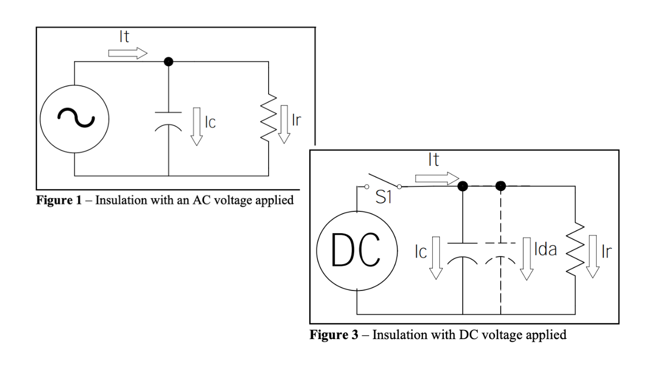
Principles of Insulation Testing
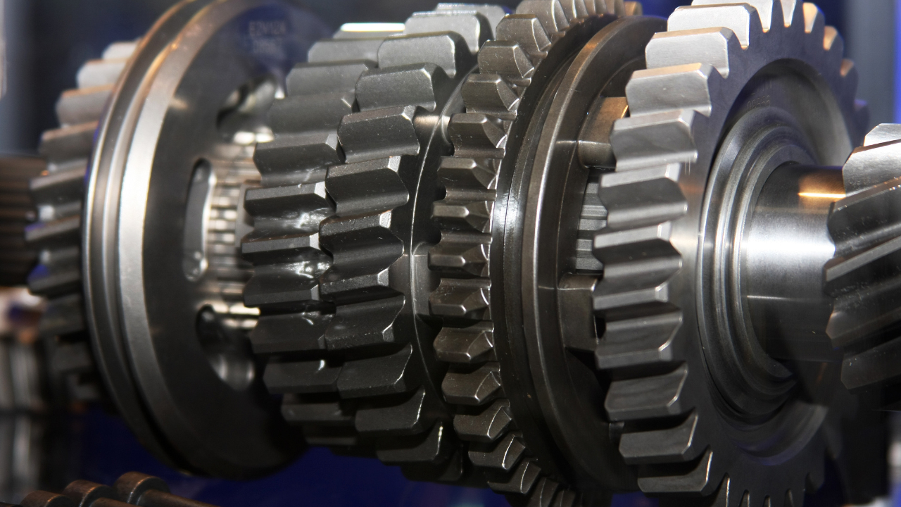
Gearbox Diagnostics Fault Detection
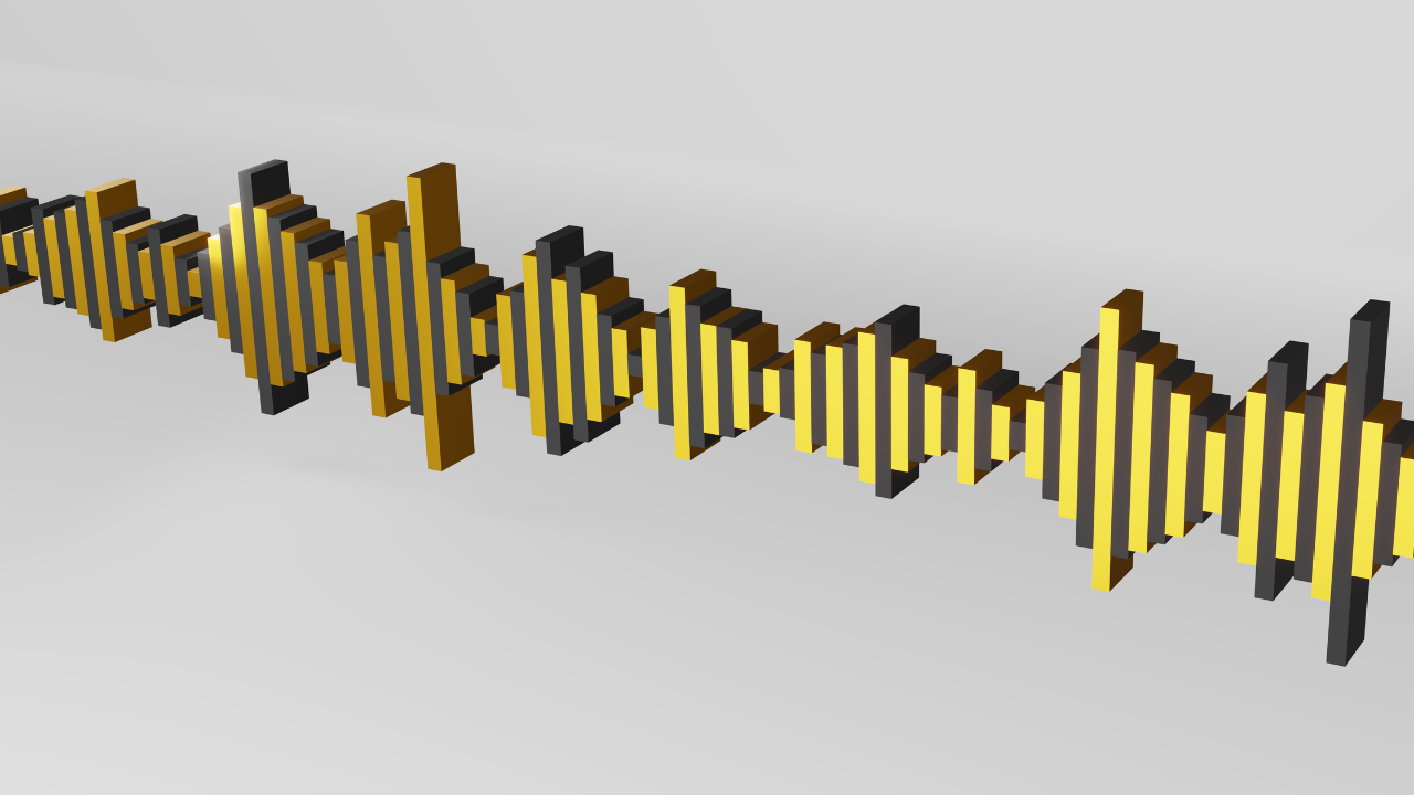
What is Vibration?

Why Record? Infrared Video
What You Should Know Before you Buy – A Guide to Buying an Infrared Camera