Solving Electrical Problems with Thermal Imaging
Mike Shekhtman, P.E., MBA, CMRP, Goodyear Tire & Rubber Co. North American Tire Manufacturing
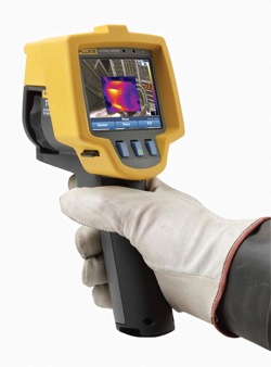
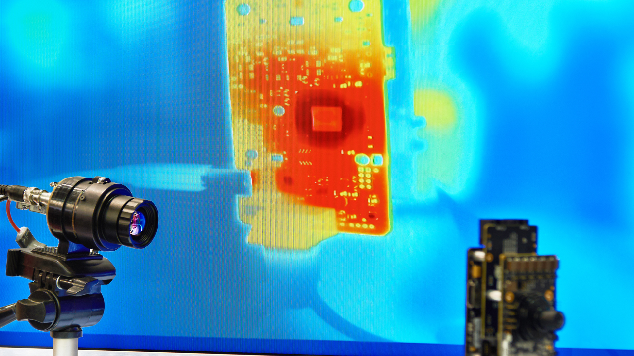
Today’s thermal imagers, which produce live images of the heat emitted from equipment, are rugged, easy to use and much more affordable than just a few years ago. This makes them highly practical and cost-effective solutions for everyday electrical maintenance. To use one, a qualified technician or electrician points the imager at the equipment in question, scans the immediate area for unexpected hot spots, then squeezes the trigger to capture a specific image. When the inspection is complete, the saved images can be uploaded to a computer for closer analysis, reporting and future trending.
Although thermal imagers may be simple to operate, they are most effective in the hands of a qualified technician who understands electrical measurement and the equipment to be inspected. For anyone using this type of imager, the following three points are especially important.
• Point 1: Loading The electrical equipment being inspected must be under at least 40% of nominal load in order to detect problems with a thermal imager. Maximum load conditions are ideal, if possible.
• Point 2: Safety Electrical measurement safety standards still apply under NFPA 70E[1]. Standing in front of an open, live electrical panel requires personal protective equipment (PPE). Depending upon the situation and the incident energy level (Bolted Fault Current) of the equipment being scanned, this may include: – Flame resistant clothing – Leather-over-rubber gloves – Leather work boots – Arc flash rated face shield, hard hat and hearing protection, or a full flash suit
• Point 3: Emissivity Emissivity describes how well an object emits infrared energy or heat. This affects how well a thermal imager can accurately measure the object’s surface temperature. Different materials emit infrared energy in different ways. Every object and material has a specific emissivity that is rated on a scale of 0 to 1.0. The higher emissivity the better it is for thermal imagers to report accurate temperatures.
Objects that have high emissivity emit thermal energy well and usually are not very reflective. Materials that have low emissivity are usually fairly reflective and do not emit thermal energy well. This can cause confusion and incorrect analysis of the situation if the user is not careful. A thermal imager can only accurately calculate the surface temperature of an object if the emissivity of the material is relatively high, and/or the emissivity level on the imager is set close to the emissivity of the object.
Most painted objects have a high emissivity of about 0.90 to 0.98. Ceramic, rubber and most electrical tape and conductor insulation have relatively high emissivities as well. Aluminum bus, copper and some kinds of stainless steel, however, are very reflective.
The good news is that most thermal imaging performed for electrical inspection purposes is a comparative— or qualitative—process. Users typically do not need a specific temperature measurement. Instead they should look for a spot that is hotter than similar equipment under the same load conditions—spots that are unexpected.
Troubleshooting Electrical Systems
There are specific things to check when chasing breaker problems or load performance issues. Once repairs are complete, another thermal scan should be obtained. If the repair was successful, the previously detected hot spot should have disappeared. (Note: Not all electrical hot spots are loose connections. For a correct diagnosis, it’s smart to have a qualified electrician either perform the thermal scan or be present while it’s completed.)
Three-phase Imbalance
Capture thermal images of all electrical panels and other high-load connection points such as drives, disconnects, controls and so on. Wherever higher temperatures are discovered, follow that circuit and examine associated branches and loads.
Compare all three phases side-by-side and check for temperature differences. A cooler-than-normal circuit or leg might signal a failed component. More heavily loaded phases will appear warmer. Hot conductors may be undersized or overloaded. However, since an unbalanced load, an overload, a bad connection and harmonics all can create a similar pattern, it is important to follow up with electrical or power quality measurements to accurately diagnose the problem. (Note: Voltage drops across the fuses and switches also can show up as unbalance at the motor and excess heat at the root trouble spot. Before it is assumed the cause has been found, double-check with both the thermal imager and a multimeter or clamp meter current measurements.)
Connections and Wiring
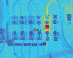
Look for connections that have higher temperatures than other similar connections under similar loads. That could indicate a loose, over-tightened or corroded connection with increased resistance. Connection-related hot spots usually—but not always—appear warmest at the spot of resistance, cooling with distance from that spot. In some cases, a cold component is abnormal due to the current being shunted away from the high-resistance connection. Broken or undersized wires or defective insulation also may be found. The NETA (Inter-National Electrical Testing Association) guidelines say that when the difference in temperature (DT) between similar components under similar loads exceeds 15 C (~25 F), immediate repairs should be undertaken.
Fuses
If a fuse shows up hot on a thermal scan, it may be at or near its current capacity. Not all problems are hot, however. A blown fuse, for example, would produce a cooler than normal temperature.
Motor Control Centers (MCC)
To evaluate an MCC under load, open each compartment and compare the relative temperatures of key components: bus bars, controllers, starters, contactors, relays, fuses, breakers, disconnects, feeders and transformers. Incorporate the foregoing guidelines for inspecting connections and fuses and identifying phase imbalance.
Transformers
For oil-filled transformers, use a thermal imager to look at high- and low-voltage external bushing connections, cooling tubes, and cooling fans and pumps, as well as the surfaces of critical transformers. (Dry transformers have coil temperatures so much higher than ambient, it’s difficult to detect problems with thermal imagery.) Incorporate the previously noted guidelines for connections and imbalances. The cooling tubes should appear warm. If one or more tubes are comparatively cool, oil flow is probably restricted. Remember: like an electric motor, a transformer has a minimum operating temperature that represents the maximum allowable rise in temperature above ambient (typically 40 C). A 10 C rise above the nameplate operating temperature will probably reduce the transformer’s life by 50%. (Note: For a thermal imager to detect an internal transformer problem, the malfunction must generate enough heat to be detectable on the outside. That means that a malfunctioning bushing connection, for example, will be much hotter than the surface temperatures read by the imager.)
Reference
1. For PPE guidelines, reference NFPA (National Fire Protection Association) Standard 70E Tables 130.7 (c)(9) (a), (c)(10), (c)(11). Michael Stuart manages thermography products for the Fluke Corporation and has previous experience in electrical and insulation resistance testing
Related Articles
Principles of Insulation Testing
Top Tips for Selecting Pressure Measurement Transmitters
Gearbox Diagnostics Fault Detection
What is Vibration?

Why Record? Infrared Video
What You Should Know Before you Buy – A Guide to Buying an Infrared Camera