Electrical Troubleshooting in 7 Steps
www.pdma.com
One of the most rewarding aspects of working as an electrician is taking such compelling evidence as “appears to be developing a problem,” determining what is actually going on, and making a sound decision on the correct course of action. Successfully troubleshooting a complex piece of equipment gives a technician a tremendous sense of satisfaction. Having an effective electrical troubleshooting plan and following it can help obtain this feeling of satisfaction.
This article presents an overview of a simple, but effective, method of investigating an electrical problem. Use this seven-step process when presented with a complex problem:
• Gather the information
• Understand the malfunction
• Identify which parameters need to be evaluated
• Identify the source of the problem
• Correct/repair the component
• Verify the repair
• Perform root cause analysis
1. Gather Information
Gathering information is a logical first step in any electric troubleshooting endeavor. Ask about or perform the following:
• What technical documentation about the equipment is available?
• How exactly is the equipment supposed to operate?
• Are there any previous lessons learned?
• Review any material history that exists for the equipment.
• Identify similar equipment to which you can compare the malfunctioning equipment. (This can be especially helpful if there is limited technical data available for the equipment that is malfunctioning.)
Let us apply step 1 to the boiler feed pump example.
For a high-cost repair like a boiler feed pump, the importance of answering or performing as many of the listed items before considering a repair activity is vital. Applying the first step resulted in a review of the equipment’s current signature analysis (CSA) and vibration analysis material history. During this review it was noted that the amplitude of the pole pass frequency in the CSA had increased for both of the motors powering the pump. However, vibration analysis did not indicate any possible problems, either mechanical or electrical.
Now that you have identified technical resources and equipment operation, you are in a position to understand the malfunction.
2. Understand the Malfunction
Understanding the malfunction means that you understand how or what the process is and what portion of the process is operating incorrectly. Answer these questions:
• How is the process supposed to work?
• What is not functioning as it should?
• What would cause these results or malfunction?
Applying step 2, the boiler feed pump in question has not been reported by operations to have a problem but the field technicians, through the use of predictive tools, have trended a possible anomaly. Rotor defects, bearing misalignment, magnetic offset, or abnormal load fluctuations were determined to be possible causes of the pole pass frequency trending upward.
3. Identify which Parameters Need to be Evaluated
Identifying which parameters need to be evaluated requires a clear understanding of the discrepancy and which signals affect the suspected component. Which input signals control the component? What is the expected output from the suspect circuit? Is there a timing delay, sequence, or set point that can be verified?
Identify the parameters that need to be recorded which could either confirm or refute your suspicions regarding the problem. Identify the following:
• What parameters can you measure?
• What are the expected values for any measurements that are to be taken?
• What test equipment is needed?
• Is there access for the required readings?
• Is there an alternative method to gather the required readings?
• Could other components have been affected by this fault?
For step 3, gaining access to the high voltage cables supplying the boiler feed pump motors would prove to be difficult. However, testing from the current and potential transformers (CTs and PTs) offers an easy alternative method to gather the required voltage and current signals to assist in electrical troubleshooting.
Having performed the first three steps, it is time to perform the required measurements and observations to identify the faulty component. Ensure that all required safety procedures are adhered to while performing any test.
4. Identify the Source of the Problem
Identifying the source of the problem requires the technician to isolate components and evaluate circuit parameters, to isolate the circuit by group when dealing with a complicated circuit (half-step approach), and to identify the malfunctioning component using the recorded data.
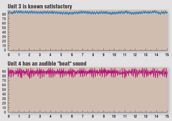
One test recommended for confirming a possible anomaly and establishing a severity is a current profile comparison between two like machines. This is sometimes referred to as a process analysis test. Fig. 1 shows current samples from two identical machines. The MCEMAX in-rush/start-up test is a capture of a single channel of RMS enveloped current for up to 60 seconds. The test has a sampling rate of 3600 samples per second and produces a digital strip chart of RMS current.
In this example there is a considerable difference between the Unit 3 and Unit 4 motors. With this limited information, a technician would at least have strong evidence that further investigation and possible action on the Unit 4 motor is necessary.
The current modulations seen in Fig. 1 will create torque variations and possible degradation of electrical and mechanical components if left alone. Step 4 calls for more detailed analysis of the data available to isolate the source of the problem. To provide further analysis from the current spectrum, Advanced Spectral Analysis (ASA) uses current demodulation to identify and separate each of the specific frequencies that are modulating the current. By correlating these frequencies to the electrical and mechanical components of the motor pump assembly, the technician can determine which component is creating the largest impact.
The demodulation process removes the 60 Hz frequency component from the captured current signal. Removing that component allows repetitive torque variations developed by mechanical items such as belts and gears, which were previously lost in the signal-to-noise ratio of the spectrum, to be identified. These mechanical frequencies are transmitted to the current signature via the air gap flux of the motor during operation.
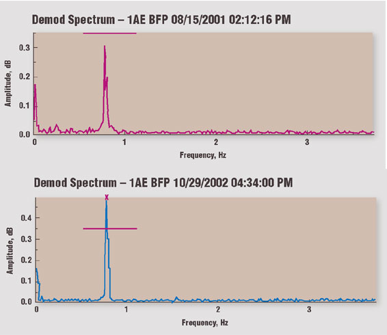
Applying step 4 to the boiler feed pump, Fig. 2 shows the demodulated current spectrums from one of the motors taken approximately 1 year apart. The pole pass frequency (FP) has been isolated for evaluation of the change in amplitude over time. The other motor had similar results. It was the increase in the FP amplitude that raised concern over the condition of the equipment.
Additional testing was performed with particular attention to evaluating the condition of the motor’s rotor. It was determined after gathering additional vibration, motor circuit analysis, and current signature data that the equipment needed to be removed from service for repairs. What made this decision especially difficult was that the vibration data was inconclusive. Of several surveys taken on the equipment at different times, only one showed any signs of increased vibration levels.
Armed with data, you now can determine what needs to be done with the suspect component. Many times after the first round of electrical troubleshooting, the first three steps may need to be repeated; however, now you have additional data to work with.
5. Correct/repair the Component
Correct or repair the component identified as damaged based on the recorded data. Perform the required repairs to the circuit. Completing step 5 can range from simple adjustments to a complete component replacement.
For the boiler feed pump, when inspecting the two motors, the technicians found that one motor had bent/damaged rotor bars. The damage to the rotor was no surprise due to the elevated pole pass frequency indications during the current signature analysis. But why only one of the rotors when both of the motors had elevated values? Technicians felt that since both motors were mounted to a common shaft, it would not be unusual for the elevated pole pass frequency of one motor to be transmitted through the shaft to the other.
In addition to the rotor bar degradation, technicians discovered severe damage to the load end bearings of each motor. During initial installation, the magnetic center was not properly set for one, or possibly both, of the motors, which led to axial thrusting of the drive shaft, causing the bearing damage. Technicians conducted inspections of similar boiler feed pump installations to ensure that both motors were properly aligned with regard to magnetic center.
6. Verify the Repair
Verify the repair after completion. Ensure the equipment is operating as designed. Perform another round of testing to verify the equipment is in fact running correctly and that no other discrepancies exist.
Following the repair and installation of the boiler feed pump motors, or the installation of replacement motors, retest to ensure the installation will not result in the same failure mechanism in the future. Looking at another example, a high resistance joint in the connection box of a 460 V ac induction motor was identified (see “High Resistance Connection Test Results”). The motor lugs were replaced and retaped, resulting in a 3 percent reduction in resistive imbalance and a cleared alarm.
7. Perform Root Cause Analysis
Performing root cause analysis, even though mentioned last, began in the first step of the electrical troubleshooting process. You should use the knowledge gained throughout the electrical troubleshooting process in determining what could have possibly caused the component to fail.
Did the component fail prematurely? Why are the motor windings failing after only four years of service? These are just a couple of the questions that may come to light when evaluating the whole repair process. Without identifying the possible cause that led to the failure, the repair will always be only temporary. While working through the electrical troubleshooting process, ask yourself, “Is this the root cause or just a symptom of the problem?”
When attempting to determine the cause of increased motor running temperature, a technician recorded the RMS current to the motor. The process powered by the motor involves constantly changing speeds and loads, shown in Fig. 3. With the in-rush/start-up current capture providing a graph of current throughout the repetitive cycle, it was readily apparent why the motor temperature was running so high. The level horizontal line indicates nameplate full load current.
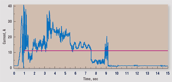
Using this data, the technicians determined that the motor was undersized for the varying load it was driving. Repairing the heat-damaged motor would not have been a permanent solution to the problem. Installing a motor only slightly larger than the original resulted in an installation where motor operating temperature is well within the temperature ratings of its insulation system.
By following a well thought-out systematic process when challenged with an electrical troubleshooting problem, you will greatly enhance your effectiveness. Invest a little time up front doing your research and determining your troubleshooting plan of action. A benefit of newer test equipment packages, which combine multiple testing technologies in one unit, is how much they increase the flexibility and capability of a technician’s troubleshooting toolbox.
Inventory your test equipment and determine what you have available when the opportunity to use the seven-step troubleshooting process presents itself.
HIGH RESISTANCE CONNECTION TEST RESULTS
| Test Date | 7/13/1998 | 7/16/1998 |
| Test ID: | 1651 | 1685 |
| Voltage | 500 | 500 |
| Motor Temp | 28 | 35 |
| Measured Mohm | >2000 | 1100.0 |
| Corrected Mohm | OVR | 780.0 |
| pF Ph 1 to Gnd | 34250 | 34500 |
| ohm Ph 1 to 2 | 0.07700 | 0.07500 |
| ohm Ph 1 to 3 | 0.07700 | 0.07450 |
| ohm Ph 2 to 3 | 0.07300 | 0.07500 |
| mH Ph 1 to 2 | 1.590 | 1.590 |
| mH Ph 1 to 3 | 1.580 | 1.585 |
| mH Ph 2 to 3 | 1.585 | 1.595 |
| % Res. Imbalance | 3.52 | 0.45 |
| % Ind. Imbalance | 0.32 | 0.31 |
| $ Power Loss | 63.23 | 7.90 |
| Condition Code | Good |
In retesting after repairs, a high resistance joint in the connection box of a 460 V ac induction motor was identified. The motor lugs were replaced and taped, resulting in a 3 percent reduction in resistive imbalance and a cleared alarm.
Information supplied by PdMA Corp., 5909-C Hampton Oaks Pkwy., Tampa, FL 33610; (800) 476-6463; e-mail pdma@ pdma.com
Related Articles

Keys for Effective Troubleshooting

Corrective Maintenance Task Generation

Availability in a Supply Constrained Environment is the #1 Issue for Refinery Executives

Weibull Point Process Applied to Repairable Subsystems

Energy Savings Through Pump Refurbishment and Coatings

Causes of Overheating in Cartridge Mechanical Seals