API Plans that I Use. 15-05
The McNally Institute
The American Petroleum Institute (API) issues guide lines to help petroleum people select and then pipe various types of controls for mechanical sealing applications. These piping arrangements are described in a series of plans issued by the API.
Although 17 plans are described, only a few are really needed. Any time you have 17 choices there is bound to be some confusion. In the following paragraphs I will describe those API plans that I use on a regular basis, where I use these plans and, in the process, hopefully simplify your selection decisions.
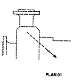 Plan #01 Discharge recirculation to pressurize the pump stuffing box.
A recirculation line is connected from the discharge side of the pump to the stuffing box. The high-pressure discharge fluid is then recirculated through the stuffing box to the rear of the impeller and eventually to the pump discharge.
This technique presents a couple of problems for maintenance people:
- If the fluid contains solids (and most of them do) the centrifugal action of the impeller will concentrate the solids on the inside diameter of the pump volute and it is this dirty fluid that is being recirculated to the stuffing box. Needless to say this will not be good for the mechanical seal because the solid particles will act as a “sand blaster” cutting into the lapped seal faces and clogging the sliding seal components.
- The pump wear rings, critical tolerances and close fitting bushings can experience rapid wear as the solids pass through these narrow clearances.
The only legitimate use of this discharge recirculation line is to pressurize the stuffing box to prevent a liquid from vaporizing, and that is where I recommend its use.
Be careful if you use this method in hot water applications especially if a heat exchanger is installed in the recirculation line. A high temperature water or steam leak in any of the fittings could be dangerous for any personnel in the area and any entrained solids can clog up the heat exchanger.
When this line is used to pressurize the stuffing box you should keep several additional thoughts in mind:
- Install a close fitting bushing in the bottom of the stuffing box. The clearance varies with the bushing material but it should be about 0.002 inches/ inch (0,002 mm/mm) of shaft diameter. This bushing will help in raising the stuffing box pressure
- Be sure to direct the discharge recirculation line away from the lapped seal faces and the thin metal plates used in a metal bellows seal.
- If you are using properly installed, balanced O-ring seals (and you should be), The sealed product will not flash between the faces as long as the stuffing box pressure is a least one atmosphere higher than the liquid vapor pressure. The discharge recirculation line should guarantee you will have this pressure difference.
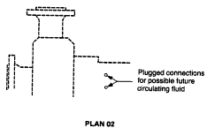 Plan #02 Circulation through a pump heating or cooling jacket
Condensate, steam, or heat transfer oils work well as the heat transfer medium
This is the best method of controlling the temperature of a fluid in the pump stuffing box if the temperature must be controlled when the pump is not running.
There should be no recirculation or flushing lines attached to the stuffing box when this environmental control is in use. Some of these lines could be covered up by insulation, so look out for them. High temperature pumps should come equipped with a cooling or heating jacket installed around the pump stuffing box. If a jacket (B) has not been installed on your pump it can probably be purchased from the pump manufacturer or an “after market” supplier.
The secret to using a jacketed stuffing box is to install a thermal bushing into the bottom of the stuffing box and then “dead end” the stuffing box liquid. Dead ending means that no suction or discharge recirculation lines should be installed. Any material that has poor thermal-conducting properties will be satisfactory for the bushing provided it is compatible with what you are sealing. Carbon is an excellent choice because unlike Teflon® it does not change dimensions too much with a change in temperature.
- A small amount of liquid or steam through the jacket can control the stuffing box to whatever temperature range you need. In some instances cool heat transfer oil is utilized. Keep in mind that this jacket may also be providing cooling to the bearing case as well as the stuffing box.
- Be sure the jacketing fluid is free from calcium (hard water) or any substance that can build a film on the inside of the jacket surface and restrict the heat transfer. A number of cleaners are available if you experience this problem. Condensate and steam are good jacketing fluids that present few clogging or film building problems, and are available in most plants.
- Remember that both condensate and low-pressure steam will cool hot oil in the stuffing box. A mixing valve can blend steam and condensate to get precise temperature control
- Its pressure determines the temperature of steam. You can monitor the steam pressure out of the heating jacket to determine the steam temperature.
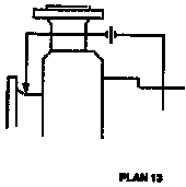 Plan #13 Suction recirculation to keep a flow going through the stuffing box
This is the best general piping layout for most of your applications
In this arrangement a line is connected between the suction of the pump and the bottom of the stuffing box or seal gland connection. Many pumps have a connection already tapped at the suction throat of the pump for a suction gage. If this fitting is available you can install one in the piping or in the pipe flange if the piping is not thick enough to be drilled and tapped.
Try to make the stuffing box connection as close to the seal faces as possible to insure a good circulation through the stuffing box.
- Stuffing box pressure is almost always higher than the suction pressure of the pump. Liquid from behind the impeller will be circulated through the stuffing box to the pump suction. The impeller has centrifuged this liquid and the result is that the liquid going into the stuffing box is considerably cleaner than what you are pumping.
- In many cases you can eliminate the need for flushing in clean liquid and diluting your product. This environment control works very well in closed impeller pump designs and those open impeller designs that adjust towards the pump volute rather than the back.
- CAUTION! You should not use suction recirculation in the following applications:
- Any time you are pumping at, or close to the product’s vapor point.
- If the fluid entrained solids have a low specific gravity. In other words, they float.
- If you are using a Duriron pump or any impeller that adjusts to the back plate.
- If you are using a double suction pump where the stuffing boxes are at suction pressure.
- Suction recirculation can also be used to lower the pressure in the pump stuffing box. A close fitting bushing must be installed into the bottom of the box to assist in establishing a pressure drop. You must be careful to insure that this bushing is secured by a snap ring or some other positive retention method to prevent the differential pressure across the bushing from blowing the bushing into the mechanical seal. If the fluid contains abrasive solids you will experience some erosion of the bushing inside diameter as the abrasive fluid accelerates through the bushing on its way to the pump suction.
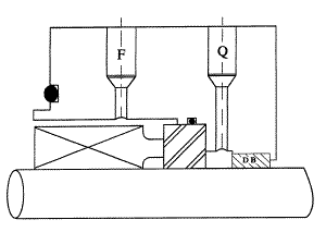 Plan #62 The quench gland. Often called the API gland
In general usage the term quench is frequently used to describe the cooling of a heated metal, or to extinguish a flame. In the seal business, quench (Q) is a term used to describe the introduction of a fluid outside the mechanical seal. We use this fluid to:
- To cool the product we are sealing
- To dilute any leakage that might migrate across the seal faces.
- To introduce low-pressure steam behind the seal to put out a fire.
- The Quench connection is labeled (Q). A close fitting bushing (DB) in the end of the gland directs the quench fluid down a drain hole on the opposite side of the seal gland
- Steam is the most popular quench medium, but care should be taken that the steam pressure is very low, or the hot steam will penetrate through the nearby bearing seals and contaminate the bearing oil.
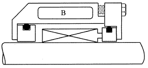
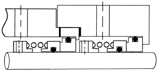 Plan #53 Barrier/ buffer fluid using an internal pumping ring
Any time you use dual seals (two seals) in an application; you should have a fluid circulating between them to prevent the generation of unwanted heat. The following illustration shows a tandem arrangement of dual rotating seals.
- If the pressure of the fluid between the seals is higher than stuffing box pressure we call it barrier fluid. If the pressure is lower than stuffing box pressure we call it buffer fluid
- The buffer/barrier liquid can be circulated either by forced circulation, a pumping ring or convection (each a different API plan number). The method that you will use will be dictated by the heat being generated by the pressure in the stuffing box, the shaft speed and shaft size. Since heat generation is also a function of seal design, all seal manufacturers provide charts or graphs to give you the correct guidelines that will insure the proper amount of circulation between the seals.
- If you elect to use a forced circulation system be sure to introduce the fluid into the bottom of the stuffing box or gland connection and out the top. This arrangement will insure that the space between the seals is vented allowing proper cooling to take place.
- Forced circulation is the recommended method with all vertical shaft applications; although it is possible to offset the centering of the seal gland and get a small amount of pumping action as the liquid circulating in the seal gland changes its velocity at the convection tank connections.
- Many of the latest seal designs utilize a built in pumping ring to enhance convection. This pumping arrangement is very necessary whenever oil is used as the barrier fluid because of oil’s low specific heat and poor conductivity.
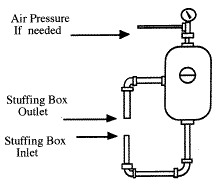 The following illustration shows a typical convection system that can be used with two balanced seals. Check with your supplier for recommended pipe size, height and length.
CAUTION! Do not hang the convection tank on the seal gland. The increased offset weight can distort the internal clearances of the gland.
- Water is one of the best barrier or buffer fluids because of its high specific heat and good conductivity. Petroleum oil is probably one of the worse because of its low specific heat and poor conductivity. Keep this in mind when you select a barrier or buffer fluid for your seals.
- The type of seal you select will determine if the fluid between the seals has to be kept higher or lower than the stuffing box pressure.
- Fluctuating pressures are normal in this business so you should select seals that are hydraulically balanced in both directions to eliminate any problems that might be caused when the barrier fluid or system pressure varies.
- Be sure to connect the convection tank or forced lubrication system so that the inlet is at the bottom of the double seal and the outlet discharges from the top of the seal. This arrangement will allow the seal to vent and insure that the passages are full of liquid.
 Plan #3 Flushing to remove unwanted fluid in the stuffing box.
Do not confuse flushing fluid with discharge recirculation, suction recirculation, quenching, barrier fluid, buffer fluid or jacketing fluid.
Flushing has a very specific meaning:
- A clean liquid from an outside source is brought into the stuffing box through a regulating valve at one atmosphere (15 psi. or 1 bar) higher than stuffing box pressure. The liquid should be brought in at the bottom of the stuffing box to insure thorough cleaning. All of this flushing liquid will eventually go into, and dilute your product.
- If you are using balanced O-ring seals you will only need enough liquid to remove solids that might interfere with the seal movement. You will not need additional liquid flow to provide cooling because balanced seals do not generate enough heat to cause heat problems in most applications.
- Seal designs that have the springs out of the fluid require only one to two gallons per hour (4 to 8 liters/hour) of flush. NOTE: this is per hour, not per minute. If you are using mechanical seal designs with multiple springs in the fluid, check with your manufacturer for his flushing recommendations.
- The clean flushing fluid can come from several sources:
- Clean water such as condensate
- Any fluid compatible with your product
- A liquid solvent for your product
- One of the ingredients in the product
- Finished product will never hurt raw product and finished product is almost always clean.
- An additive that is going to be put into the product down-stream that can be added at the pump stuffing box instead.
- If you are using shop water as the flush, you must be careful or solids in the flushing water will clog up the flow control valve. The shop water pressure also tends to vary through out the day and in some instances it can fall below the pump stuffing box pressure. Most states require an air gap in the line if you want to use shop or city water as a flushing medium. A back flow preventer valve is used many times but it is illegal in many states. Check your local regulations.
When you should use flushing plan #32?
- To introduce clean liquid into the stuffing box that will remove solids or any problem fluid.
- To cool a hot liquid by flushing in a cold one.
- To replace a liquid that is sensitive to changes in either temperature and/ or pressure.
- CAUTION! Do not be tempted to use flushing to substitute a non-corrosive liquid for a corrosive liquid and thereby save the cost of expensive seal components. Someone is going to shut off the flush for sure, and the incompatible seal components will be chemically attacked and the seal will fail prematurely.
Here are some of my comments about each of the plans recommended by the API:
Plan 01 A line from the pump discharge is connected to the pump stuffing box. We discussed this one as a legitimate method of raising stuffing box pressure
Plan 02 The stuffing box is dead-ended. Heating or cooling fluid is circulated through the stuffing box jacket. This is the best method of controlling thew stuffing box temperature when the pump is not running.
Plan 11 A line is connected from the discharge side of the pump and recirculated through an orifice into the gland flush connection. Orifices are hard to size and since many pumping fluids contain solids orifices are easy to clog.
Plan 12 A line is connected from the discharge side of the pump and recirculated through a strainer and control orifice to the gland flush connection. If solids are present in the fluid the strainer will frequently clog along with the orifice
Plan 13 A line is connected from the bottom of the stuffing box, through a flow control orifice, to the suction piping. Controlling the size of the orifice to get exactly the right flow is difficult. In most cases you will not need the orifice
Plan 21 Discharge recirculation through a flow control orifice and cooler into the seal chamber. You are cooling with high-pressure, pump discharge fluid. Not too good an idea! Hot, high-pressure fluids can be dangerous if the cooler or its inlet and outlet-line fittings leak. There are better cooling methods that utilize lower fluid pressure. Jacketing, barrier fluid and quenching come to mind. Also note that with this arrangement you only get the cooling effect when the pump is running. This could cause a premature seal failure when the pump stops.
Plan 22 Discharge recirculation is passed through a strainer, orifice and then through a cooler to the stuffing box. The above mentioned problems with the cooler, orifice and strainer can combine together for a real problem
Plan 23 A pumping ring is installed in either the stuffing box or within the mechanical seal components that will pump the stuffing box fluid through an external cooler and then back to the stuffing box. This is a good arrangement because it uses lower pressure cooling fluid. You find this arrangement on the stuffing box of many boiler feed pump sealing applications.
Plan 31 Discharge recirculation through a cyclone separator to the stuffing box, Cyclone separators are not very effective in removing the solids that fail mechanical seals. I would not waste my time with this one.
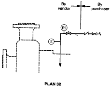
Plan 32 Flushing liquid from an external higher pressure source to the stuffing box. A good solution if you can tolerate some product dilution and insure the flushing pressure remains higher than the stuffing box pressure.
Plan 41 Discharge recirculation through a cyclone separator and cooler to the stuffing box. This combines two problems into a bigger problem.
Plan 51 An external reservoir providing a dead ended blanket of fluid to the quench connection of the API gland
Plan 52 External reservoir providing buffer fluid for the outer seal of an un-pressurized dual seal arrangement. During operation an internal pumping ring provides circulation. The reservoir is connected to a vapor recovery system and is maintained at a pressure less than the pressure in the seal chamber. This is a common and good environmental control. If the inner mechanical seal is hydraulically balanced in both directions you can use this arrangement most of the time.
Plan 53 Pressurized external barrier fluid reservoir supplying clean fluid to the seal chamber. Circulation is by an internal pumping ring. Reservoir pressure is greater than the process pressure being sealed. Typically used with a tandem dual seal. Likewise a good environmental control when the pumping fluid is dangerous.
Plan 54 Pressurized external barrier fluid reservoir or system supplying clean fluid to the seal chamber. Circulation is by an external pump or pressure system. Reservoir pressure is greater than system pressure being sealed. Typically used with tandem dual seal. Another good environmental control
Plan 61 Tapped connect for purchaser’s use. (flush connection). We discussed flush a little earlier
Plan 62 External fluid source providing a quench (steam is the most common quench fluid). Typically used with a close fitting bushing in the rear of the gland to prevent the steam from entering into the bearing cavity. A good environmental control. We discussed it earlier.
Related Articles

OEE: Overall Equipment Effectiveness
What the Pump Was Designed to Do and Why it Doesn't Do it
What is Wrong with the Modern Centrifugal Pump?

Digging Up Savings: Go with the Flow
Chain Drive Design Recommendations
Classifying Chemicals to Assure Effective Sealing